Pump sizing in critical hydrocarbon and petrochemical applications carries incredibly high stakes. Oversizing your equipment leads directly to wasted energy and excessive mechanical vibration. Undersizing causes rapid cavitation and premature bearing failure. Both errors halt industrial production entirely. Determining the correct capacity requires more than matching basic flow rates and head figures. You must align your system's hydraulic performance directly against stringent API 610 (12th Edition) reliability standards. This standard ensures equipment survives punishing refinery environments. We created this guide to help you navigate these complex sizing requirements. You will learn a structured framework to calculate exact capacity needs accurately. We also evaluate standard operating regions against extreme edge-case scenarios. Finally, we provide actionable steps to shortlist the right equipment for your facility. You can then specify a robust pumping system built for long-term operational stability.
Start by evaluating the fundamental hydraulic requirements of your facility. A highly reliable system requires accurate baseline data before you even examine manufacturer curves. You must establish strict api 610 centrifugal pump specifications to prevent catastrophic operational failures.
Understanding where your unit operates on its performance curve dictates its mechanical lifespan. The standard heavily emphasizes operating within specific hydraulic boundaries. You must balance the Preferred Operating Region (POR) against the Allowable Operating Region (AOR).
Aim for the ideal scenario within the POR. The Best Efficiency Point (BEP) represents the exact capacity where hydraulic forces balance perfectly inside the casing. Fluid moves through the volute smoothly. Vibration drops to its absolute lowest level. The POR typically spans between 70% and 120% of the BEP capacity. Running your equipment within this window ensures maximum mechanical reliability. Balanced hydraulic loads minimize stress on the shaft and bearings. Seal life extends significantly. Operators experience fewer unexpected maintenance shutdowns.
Operating outside the POR introduces complex engineering realities. Many facilities cannot keep their flow rates perfectly stable year-round. Process demands fluctuate constantly. You might need to operate within the wider Allowable Operating Region (AOR). The AOR spans the extreme limits where the manufacturer permits operation. Flow rates here are either much lower or much higher than the BEP. Running near the edges of the AOR increases internal turbulence dramatically. Radial loads on the impeller spike to dangerous levels. These intense forces attempt to bend the rotating shaft during operation.
Implement strict risk mitigation strategies if operation in the AOR is unavoidable. Standard configurations will fail prematurely under extreme radial loads. You must modify the equipment proactively.
Every capacity requirement demands a specific structural footprint. You cannot force a single design style to handle every flow rate safely. Selecting the right api 610 centrifugal pump requires matching your calculated capacity to standard industry configurations.
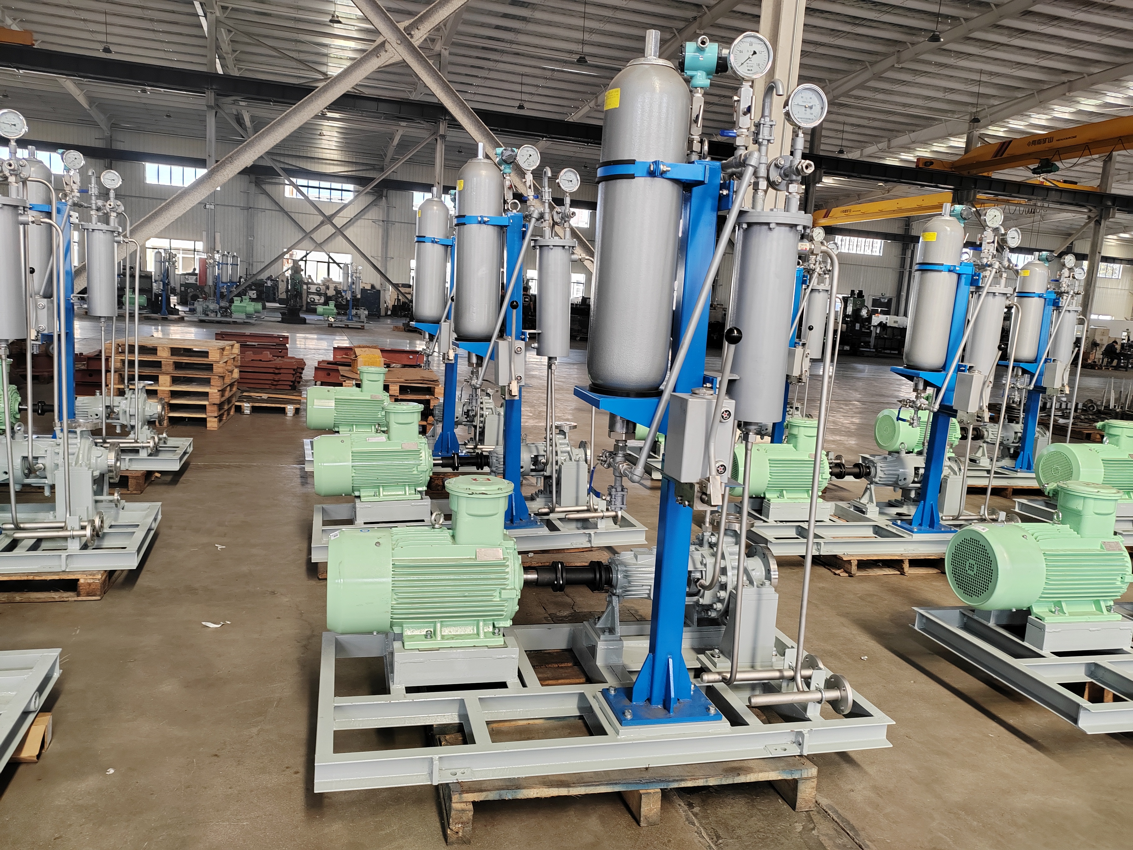
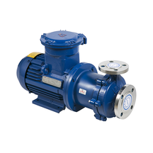
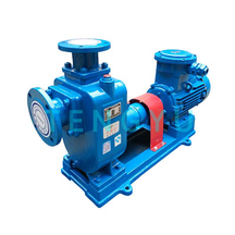
Overhung (OH) Pumps (OH1-OH6) work best for lower to medium capacities. These units feature an impeller mounted on the end of a cantilevered shaft. They handle moderate pressure environments perfectly. However, they possess inherent mechanical limitations. Pushing an OH pump beyond its standard capacity limits creates massive radial forces. These forces cause severe shaft deflection. The cantilevered design simply cannot support extreme hydraulic loads without flexing.
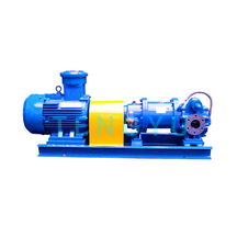
Between Bearings (BB) Pumps (BB1-BB5) excel in high-capacity applications. The impeller sits securely between two heavy-duty bearing housings. This design provides maximum rotor stability. BB pumps dominate heavy-duty pipeline and refinery applications globally. They easily handle high-pressure and multi-stage fluid requirements. The fully supported shaft prevents deflection even when operators push capacities to the extreme edges of the curve.
Vertically Suspended (VS) Pumps (VS1-VS7) solve unique spatial and suction challenges. Facilities often lack the physical footprint for large horizontal units. VS pumps fit perfectly into sump or pit applications. They also solve low-NPSHa problems by submerging the first-stage impeller deeply into the fluid reservoir. This vertical configuration maintains specific capacity volumes when surface-level suction remains impossible.
API 610 Pump Configuration Comparison
| Configuration Type | Ideal Capacity Range | Primary Advantages | Common Limitations |
|---|---|---|---|
| Overhung (OH Series) | Low to Medium | Compact footprint, accessible maintenance | High risk of shaft deflection at extreme capacities |
| Between Bearings (BB Series) | High to Very High | Superior rotor stability, handles high pressures easily | Large footprint, complex alignment procedures |
| Vertically Suspended (VS Series) | Variable | Solves low NPSHa, minimal surface footprint | Requires deep sumps, difficult internal access |
Handling hazardous fluids demands specialized hydraulic considerations. Severe chemical environments change how rotating equipment performs over time. You must adjust your capacity models when deploying an api 610 industrial chemical transfer centrifugal system.
Account for corrosion and material allowances strictly. Aggressive chemicals attack internal components relentlessly. Corrosion slowly eats away at the impeller vanes and casing walls. This continuous degradation increases the internal clearances over time. Wider clearances cause fluid to slip backward from the discharge to the suction side. This internal recirculation effectively reduces long-term capacity. The unit loses operating efficiency rapidly. You must select highly resistant alloys to maintain baseline performance.
Prepare for extreme temperature variations. Chemical transfer often involves highly heated or cryogenically cooled fluids. Thermal expansion impacts capacity handling directly. Metal components grow or shrink based on the fluid temperature. This expansion alters the critical internal geometry. Engineers must calculate these dimensional changes and select specific API material classes. Standard cast iron will shatter under thermal shock. You need robust material classes like S-6, C-6, or A-8. These upgraded materials maintain critical clearances despite extreme heat.
Evaluate seal chamber requirements carefully. Operating capacity directly dictates your mechanical seal selection. High flow rates generate higher pressures inside the seal chamber. You must comply with API 682 standard seal plans to prevent hazardous leaks. A failing seal during chemical transfer creates severe safety and environmental hazards. Match the seal flush plan to the specific capacity and pressure profile of the fluid. Keep the seal faces cool and perfectly lubricated at all times.
Finding the right equipment means finding the right manufacturing partner. You cannot trust your critical infrastructure to unverified vendors. You must rigorously vet your api 610 centrifugal pump supplier before finalizing any purchase orders.
Demand total performance testing transparency. Reliable suppliers provide certified, closed-loop performance testing. They must prove the unit meets your specific capacity curve on the test stand. Do not accept purely theoretical curves. Demand physical test data before the equipment ships. This testing verifies head, flow, vibration limits, and bearing temperatures under actual operational loads.
Verify strict compliance with 12th Edition updates. The standard evolves constantly to address industry failures. The latest edition includes stringent reliability and maintainability upgrades. Ensure the supplier strictly adheres to these current standards. Some vendors attempt to sell legacy models simply branded as compliant. You must verify their designs meet the specific dimensional and testing criteria of the newest edition.
Assess their engineering and customization support. A credible supplier behaves like a true engineering partner. They will review your capacity data critically. They will push back on unrealistic operational specifications. They offer precise hydraulic modifications rather than selling an off-the-shelf mismatch.
Check lifecycle and aftermarket availability. Industrial pumps operate continuously for decades. You must verify the long-term availability of OEM parts. Ensure the supplier maintains robust regional service networks. Quick access to replacement wear rings, impellers, and bearings is mandatory. Fast aftermarket support maintains your capacity efficiency over the pump's 20-plus-year expected lifespan.
Specifying industrial rotating equipment requires careful analytical balance. You must harmonize hydraulic math, structural configuration, and strict standards compliance. Avoid relying on generic estimates for your flow and head requirements. We encourage project engineers and procurement teams to finalize their system curves completely. Gather exact fluid data before engaging any vendors. Small variations in viscosity or specific gravity alter capacity needs drastically. Take action now by reviewing your current facility schematics. Request a detailed technical consultation from a certified manufacturer. Submit your finalized project specifications to receive a precise hydraulic evaluation and a customized equipment quote.
A: Engineers typically add a safety margin of 10% to the normal operating flow. This addition defines the rated capacity. This practice prevents undersizing the equipment and ensures it handles unexpected process surges safely. However, avoid adding excessive margins, which force the pump to operate far from its best efficiency point.
A: No. Operating below the MCSF causes extreme mechanical risks. The fluid overheats rapidly, leading to severe cavitation. Vibration spikes violently, causing imminent shaft or bearing failure. If low capacity operation is unavoidable, you must install automated minimum flow bypass valves to protect the equipment.
A: The 12th Edition introduces tightened vibration limits and much stricter testing criteria. It demands rigorous physical proof of performance. Manufacturers must demonstrate that pumps actually run reliably at their rated capacities under specific tolerances. This update eliminates theoretical sizing loopholes found in older standard editions.