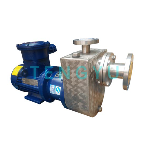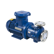
Transferring hazardous, volatile, or high-value fluids from negative suction heads presents significant operational risks. Facilities extracting chemicals from underground tanks or top-loading railcars demand absolute reliability. Any system failure during this process can trigger severe environmental and safety hazards. Standard centrifugal pumps consistently struggle to handle air entrainment. They often lose prime during critical start-up phases. Meanwhile, traditional mechanically sealed pumps introduce inevitable leakage risks over extended operation. These conventional systems simply fall short under complex lifting conditions. We will explore how pairing a self priming magnetic pump alongside a suction tank offers a specialized, zero-leakage solution. You will learn the mechanical advantages of this specific configuration. We also cover essential material selection, system sizing rules, and critical maintenance realities to ensure a safe, efficient deployment.
Many facilities traditionally rely on foot valves paired with mechanically sealed self-priming pumps. This conventional approach frequently leads to unavoidable maintenance overhead. Foot valves routinely clog or fail to seat properly. Mechanical seals inevitably wear down over time. When seals degrade, they release fugitive emissions into the surrounding environment. These leaks trigger severe EPA and OSHA compliance violations. Facilities then face steep fines and forced operational downtime.
The magnetic drive design completely eliminates these specific failure points. A sealless pump utilizes an advanced magnetic coupling to drive the internal impeller. An external drive magnet connects directly to the motor. It rotates around a stationary containment shell. Inside this shell, an internal magnet connects to the impeller assembly. The magnetic force transfers torque directly through the solid shell barrier. This creates an absolute hermetic seal. Process fluid remains fully contained within the pump casing.
Deploying this technology guarantees measurable operational success. Facilities eliminate routine seal replacement tasks. They avoid expensive environmental remediation costs entirely. By removing the risk of toxic leaks, plant managers maximize operator safety during volatile fluid transfers. The financial and safety benefits heavily outweigh initial installation complexities.
Engineers do not deploy sealless self-priming systems for basic water transfer. They reserve this configuration for highly specific, high-risk operational scenarios. Understanding these strategic use cases helps you justify the system upgrade.
Choosing the correct metallurgy directly dictates the lifespan of your pumping system. Engineered plastics work well for ambient water, but industrial applications demand robust metallic solutions. An SS304 self-priming magnetic pump offers excellent operational fit for specific chemical families.
Stainless Steel 304 significantly outperforms engineered plastics in challenging environments. It provides superior thermal stability for high-temperature hydrocarbon processing. SS304 also demonstrates exceptional resistance to industrial solvents like toluene and acetone. Furthermore, metallic casings offer vital durability against mild mechanical shocks. Plastics often crack under piping stress, but stainless steel maintains structural integrity.
However, you must recognize where SS304 fails. Highly aggressive chlorides will cause rapid pitting and stress corrosion cracking in standard stainless steel. Strong acids, such as concentrated sulfuric or hydrochloric acid, will destroy an SS304 containment shell within hours. When handling these aggressive chemicals, you must pivot to PTFE or PFA-lined alternatives.
You should carefully analyze the cost-to-lifespan ratio. SS304 units demand a higher upfront capital expenditure compared to basic cast iron or polypropylene. Yet, in compatible chemical environments, they deliver a massive return on investment. The prolonged operational lifespan and eliminated repair cycles easily offset the initial purchase premium.
Proper system sizing requires precise hydraulic calculations. Guesswork leads to immediate mechanical failure. You must carefully evaluate the relationship between the pump, the suction tank, and the piping layout.
The suction tank sizing logic follows a strict mathematical rule. The tank volume must comfortably exceed the total volume of the empty suction piping. When the pump starts, it draws liquid from the suction tank to create a vacuum. If the tank is too small, the pump exhausts its priming liquid before evacuating all the air from the lines. The system will fail to prime and immediately run dry.
You must also master NPSH (Net Positive Suction Head) calculations. The available head (NPSHa) in your system must always exceed the pump's required head (NPSHr). You calculate NPSHa by factoring in absolute atmospheric pressure, static lift height, vapor pressure, and friction loss across the piping. If NPSHr exceeds NPSHa, the fluid will boil inside the casing, causing destructive cavitation.
| Variable | Impact on System Performance | Control Method |
|---|---|---|
| Atmospheric Pressure | Higher altitude decreases available NPSHa. | Adjust calculations based on facility elevation. |
| Static Lift Height | Deeper tanks reduce available suction pressure. | Minimize vertical distance between pump and fluid level. |
| Friction Loss | Long pipes and elbows consume energy. | Increase pipe diameter and reduce sharp bends. |
| Vapor Pressure | Hot fluids vaporize easily, destroying prime. | Maintain fluid temperatures below boiling thresholds. |
Finally, evaluate the specific gravity of your process fluid. Magnetic couplings have strict torque limits. Pumping high-density fluids requires more energy. If the fluid density exceeds the magnetic torque rating, magnetic decoupling occurs. The internal magnet slips out of sync with the external drive. The motor continues spinning, but the impeller stops entirely.
Magnetic drive systems demand strict operational discipline. While they eliminate seal leaks, they introduce unique vulnerabilities. You must train operators to recognize and mitigate these specific implementation risks.
Dry running stands as the most critical vulnerability. Sealless pumps rely entirely on the process fluid for internal bearing lubrication. They utilize silicon carbide bearings. These bearings generate intense friction without liquid. Despite the protective suction tank, extended dry-running during a failed prime will cause catastrophic bearing failure in minutes.
Furthermore, magnetic pumps are completely intolerant to solids. The internal clearances between the impeller and containment shell are incredibly tight. Abrasives or hard particulates in the fluid will rapidly destroy the internal containment shell. They will also score the silicon carbide bearings. You must install high-quality suction strainers. However, operators must monitor these strainers daily. A clogged strainer dramatically alters your NPSHa, leading straight back to cavitation.
Heat generation poses another maintenance reality. The magnetic eddy currents passing through the metallic containment shell generate friction. This friction transfers heat directly to the process fluid. During closed-loop priming phases, temperature spikes happen rapidly. You must monitor casing temperatures carefully to prevent volatile fluid vaporization inside the pump.
| Risk Factor | Symptom | Required Mitigation Strategy |
|---|---|---|
| Dry Running | Screeching noise, sudden motor load drop. | Install power monitors to trip the motor on low load. |
| Solid Particulates | Vibration, scoring on shell, flow reduction. | Deploy dual-basket strainers and monitor differential pressure. |
| Heat Generation | Casing excessively hot, vapor lock. | Install PT100 temperature sensors on the containment shell. |
Moving from concept to procurement requires a methodical approach. You cannot simply order a standard pump off a catalog page. Successful deployment relies on rigorous data collection and careful vendor selection.
Consider referencing industry standards like API 685 when evaluating sealless pumps for petroleum applications. These frameworks ensure your shortlisted equipment meets rigorous structural and safety requirements.
The combination of a self-priming magnetic pump and a suction tank delivers a highly effective solution for challenging, negative-lift applications. By eliminating mechanical seals, facilities drastically reduce hazardous emissions and routine maintenance interventions. We explored how this setup handles top-unloading tasks and manages high-vapor-pressure fluids safely.
Successful deployment hinges completely on strict adherence to hydraulic calculations. You must respect fluid compatibility constraints and accurately calculate your NPSHa. Always ensure your suction tank volume exceeds your empty piping volume.
Do not finalize your system design in isolation. Consult directly with an experienced pump engineer. Submit your exact system schematics and fluid profiles for a custom sizing evaluation to guarantee long-term operational safety.
A: It evacuates the air to draw the liquid up, but once the pump is turned off, fluid in the suction line will drop back down unless a check valve is installed. The fluid in the pump casing and suction tank remains to prime the next cycle.
A: Lift time depends on suction pipe diameter, lift height, and pump speed. It typically ranges from 1 to 5 minutes. If it exceeds this, the suction tank may be undersized or there is an air leak in the piping.
A: No. While the suction tank provides an initial buffer of liquid to allow the pump to pull air from the empty line, the pump itself must never run completely dry, as the internal bearings require fluid for lubrication and cooling.