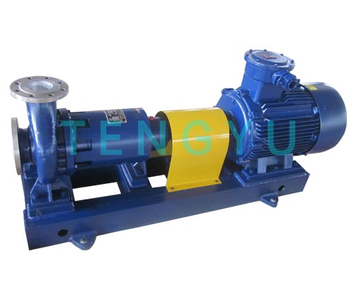
Sourcing a sealless pump fundamentally revolves around operational risk mitigation. You must eliminate mechanical seal failures when handling hazardous, toxic, or high-value chemicals. A single process leak can halt plant production and severely compromise environmental safety. Traditional sealed units often fall short in these extreme operational environments.
However, evaluating technical parameters often presents a harsh engineering reality. Over-specifying inflates initial resource allocations unnecessarily. Conversely, under-specifying leads directly to magnetic decoupling, chemical degradation, or catastrophic dry-run failures. Finding the exact performance threshold remains critical for long-term operational stability. Process engineers need a precise method to balance aggressive operational demands against physical equipment limitations.
We will explore the critical technical parameters you must evaluate before making a final sourcing decision. You will learn how fluid dynamics, material selection, and strict industry standards dictate equipment reliability. Our guide unpacks everything from magnetic material thermal limits to essential industry certifications. This compliance-aware framework helps ensure your operations run safely and efficiently.
Fluid Properties Dictate Tolerances: Specific gravity, vapor pressure, and viscosity directly determine the required torque of the magnetic coupling.
Material Selection is Binary: Wetted materials and containment shells must strictly align with the chemical compatibility matrix and maximum operating temperatures to prevent eddy current losses or corrosion.
Standardization Matters: Evaluating API 685 versus ANSI/ASME standards ensures the pump meets the specific safety and structural requirements of your operating environment.
Supplier Capabilities: A verified magnetic drive pump supplier should provide transparent hydraulic curves, NPSH requirements, and verifiable localized support.
Understanding your fluid dynamics is the absolute first step in equipment selection. You cannot accurately specify a magnetic drive pump without defining exactly how the liquid behaves under operational pressure and temperature.
You must establish a precise duty point for your system. Review the manufacturer performance curve closely. Ensure the equipment operates as near as possible to its Best Efficiency Point (BEP). Operating too far to the left or right of the BEP causes internal radial thrust imbalances. These imbalances place excessive stress on the internal sleeve bearings, shortening equipment lifespan significantly.
Calculating the available versus required suction head is critical. You must verify that Net Positive Suction Head available (NPSHa) comfortably exceeds Net Positive Suction Head required (NPSHr). Sealless designs are exceptionally susceptible to cavitation. Cavitation vapor bubbles disrupt the crucial fluid film lubricating the internal bearings.
Calculate static head pressure at the suction inlet.
Subtract friction losses from piping and valves.
Subtract the absolute vapor pressure of the fluid at operating temperature.
Ensure the final NPSHa value exceeds the manufacturer’s NPSHr by at least 1 meter (3 feet).
Fluid weight and thickness directly dictate your power requirements. Higher specific gravity fluids demand higher motor horsepower. They also require significantly greater magnetic coupling strength to prevent slip. Viscosity poses another hard limit. Engineers typically cap allowable viscosity around 200 cSt for standard units. High viscosity fluid severely dampens centrifugal impeller action. It drastically reduces overall hydraulic efficiency and increases internal heat generation.
You must actively assess the fluid vapor pressure against maximum operational temperatures. Heat accumulates inside the rear containment shell due to magnetic losses. If the fluid temperature breaches its boiling point inside this enclosed space, it flashes into vapor. Vapor locking immediately starves the bearings of lubrication, leading to sudden mechanical failure. Always maintain a strict thermal safety margin.
Chemical aggression limits your material choices strictly. You must match the casing, shell, and internal bearings perfectly to the process fluid. A single mismatched component compromises the entire pressure boundary.
You generally face two primary paths for casing and impeller materials: non-metallic and metallic. Non-metallic lined units utilize ETFE or PFA polymers. These heavy-duty plastics excel in highly corrosive environments involving strong acids or concentrated alkalis. They resist chemical attack exceptionally well. Metallic options include 316 Stainless Steel, Hastelloy, or Alloy 20. You specify metallic casings primarily for high-temperature applications or when handling mildly abrasive process fluids where plastic linings would degrade.
The containment shell acts as the primary atmospheric barrier. It separates the process fluid from the external environment. Your choice here heavily impacts both safety and energy efficiency.
Shell Material Type | Primary Advantages | Key Limitations | Best Use Cases |
|---|---|---|---|
Metallic (Hastelloy, Titanium) | High pressure and high temperature tolerance; extreme structural durability. | Susceptible to magnetic eddy currents; generates excess internal heat. | High-heat petrochemical processing; high system pressure lines. |
Non-Metallic (Carbon Fiber, PEEK) | Zero eddy current losses; operates much cooler; highly efficient. | Strict limits on maximum temperature and system pressure spikes. | Standard chemical processing; temperature-sensitive fluids. |
Internal bearings support the rotating impeller assembly entirely within the fluid. Silicon carbide (SiC) remains the prevailing industry standard here. SiC offers extreme surface hardness and near-universal chemical resistance. It easily handles continuous operation in aggressive fluids. However, SiC is notoriously brittle and shatters under thermal shock. If your system risks occasional dry running, you may specify specialized carbon graphite bearings instead. Carbon graphite provides a softer wear profile and offers limited survivability during short dry-run events.
When specifying a magnetic drive coupling centrifugal pump, understanding the internal magnetic arrays is non-negotiable. The magnets transmit all motor torque through a solid barrier. This invisible mechanical link requires precise engineering.
Engineers primarily rely on two distinct rare-earth magnetic materials. Neodymium Iron Boron (NdFeB) offers incredibly high magnetic strength. It remains highly cost-effective for standard applications. However, NdFeB is highly susceptible to thermal demagnetization. You must strictly limit its use to environments below 150°C (300°F). For high-heat applications, Samarium Cobalt (SmCo) becomes mandatory. SmCo magnets maintain their structural and magnetic integrity at much higher temperature thresholds. They operate reliably up to approximately 315°C (600°F) without losing their holding force.
You must ensure the specified magnetic coupling rating comfortably exceeds your maximum required torque. Standard engineering practice dictates at least a 15% to 20% safety margin above the highest anticipated load. This calculation must include startup inertia spikes and temporary cold-fluid viscosity increases. If demand exceeds the magnetic force, the coupling slips. This condition is called decoupling. Once decoupled, the outer drive magnet spins rapidly while the inner impeller remains stationary. This friction generates massive, destructive heat almost instantly.
Evaluate the manufacturer’s specific design for internal fluid circulation. A portion of the pressurized process fluid must bypass the impeller. It flows backward over the inner magnetic rotor and passes through the internal bearing channels. This circulation path dissipates the inevitable heat generated by the spinning magnets. It also provides a constant liquid film for the SiC bearings. Without a well-engineered cooling path, the fluid boils, leading to rapid bearing failure.
Industrial environments do not tolerate uncertified equipment. You must map your operational requirements against recognized global engineering standards. Proper certification ensures baseline safety and physical interchangeability.
Heavy industries rely heavily on standards to guarantee reliability. API 685 represents the gold standard for heavy-duty petrochemical, oil, and gas applications. This standard mandates incredibly thick casings, strictly defined bearing lifespans, and massive structural safety margins. It ensures the equipment survives severe pipeline stress.
Conversely, ANSI/ASME standards apply perfectly to standard chemical processing facilities. These standards focus on dimensional interchangeability. You can swap one ANSI-rated unit for another without modifying your existing piping or foundation pads. They offer a highly streamlined approach for general industrial use.
Handling flammable liquids demands strict electrical and mechanical safety compliance. If you operate in designated hazardous environments, verify ATEX certifications thoroughly. The combined pump and motor unit must meet regional explosion-proof directives. This certification ensures the equipment will not generate stray sparks or excessive surface heat capable of igniting atmospheric vapors.
Lethal fluid services require secondary safety nets. Evaluate the availability of secondary containment mechanisms. Advanced units utilize double containment shells or specific lip seals on the drive shaft. Furthermore, integrating leak detection instrumentation is vital. You should install active power monitors to detect torque drops instantly. Adding temperature probes inside the magnetic shroud provides early warning of internal heat accumulation before a catastrophic breach occurs.
Equipment quality means little without competent engineering backing. Choosing the right magnetic drive pump supplier ensures you receive a properly engineered unit suited to your exact process realities.
The supplier must demonstrate deep technical expertise. They should proactively help you review all necessary magnetic drive pump specifications. Demand a partner who analyzes your specific gravity, vapor pressure, and chemical compatibility charts meticulously. Avoid vendors who merely push off-the-shelf units without questioning your system parameters. A reliable partner acts as a consultant, identifying potential cavitation risks or thermal bottlenecks before they happen.
Never accept industrial equipment without rigorous proof of performance. You must demand certified performance curves generated directly from factory test stands. Request comprehensive hydrostatic test reports to prove casing integrity under pressure. Furthermore, insist on material traceability certificates. Industry standards like EN 10204 3.1 trace the exact metallurgical origins of the wetted components. This documentation proves the metal alloys meet your required corrosion resistance standards.
Evaluate the long-term operational alignment of the equipment. Review the availability of critical spare parts, such as replacement cartridge kits, O-rings, and silicon carbide bearings. Assess the vendor's local service capabilities and field engineering reach. Strong warranty terms and rapid local deployment minimize your unplanned downtime. A vendor with robust regional stock guarantees you will not wait weeks for overseas shipping when an unexpected failure halts your production line.
Balance Operational Realities: Selecting the proper technical specifications requires harmonizing hydraulic needs, chemical realities, and structural industry standards. You must align every material choice with the process fluid.
Prioritize Safety Margins: Always engineer a 15-20% margin into your magnetic torque requirements. Respect thermal limits strictly to prevent internal flashing and subsequent bearing failure.
Execute a Structured Action Plan: Compile all your specific fluid data into a detailed RFQ. Include chemical makeup, maximum operating temperature, specific gravity, and the precise flow and head requirements.
Engage Experts: Submit your structured data to technically proficient suppliers. Force them to model the exact specifications against your facility's operational constraints before approving any design.
A: Standard magnetic drive pumps cannot run dry. The internal process fluid acts as the primary lubricant and coolant for the internal bearings. Dry running causes rapid overheating and catastrophic bearing failure. However, specific bearing materials like specialized carbon graphite can offer temporary, highly limited dry-run protection during short process upsets.
A: Decoupling occurs when the torque required by the impeller exceeds the magnetic force of the coupling. Sudden system pressure spikes, uncalculated specific gravity increases, or debris jamming the impeller trigger this failure. Once decoupled, the motor spins freely, but the impeller remains stationary, generating immense and destructive internal heat.
A: Generally, no. Manufacturers design them specifically for clean liquids. Hard solids rapidly damage the internal bearings or block the narrow internal cooling passages. If solids are present, you must specify specialized suction strainers or strictly evaluate custom hardened bearing designs to prevent premature equipment failure.