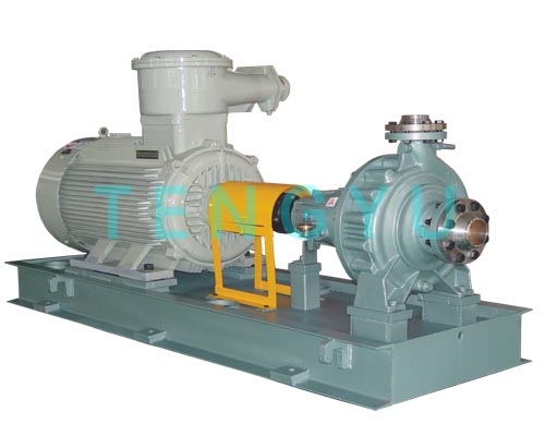
Engineers and procurement teams need a definitive, standardized understanding of pump configurations within petrochemical and hydrocarbon processing. The backbone of modern fluid transfer relies heavily on precise equipment designations. An OH type pump serves as a critical asset in these rigorous environments. We define it as a centrifugal pump featuring a specific mechanical layout. You will find its impeller mounted securely on the end of a cantilevered shaft. The suction side remains completely unsupported. We rely on this unique design to move highly volatile liquids safely.
Proper specification of an API 610 OH pump directly optimizes asset lifecycle efficiency and operational reliability. You must balance strict reliability mandates against upfront capital boundaries. This comprehensive guide explores the foundational mechanics governing these cantilevered units. You will uncover industry classification standards, structural differences, and critical decision thresholds. Read on to master the framework guiding optimal overhung unit selection.
Classification: OH pumps feature a cantilevered shaft design and are primarily categorized into OH1 through OH6 under API 610 guidelines.
Application: Best suited for moderate flow and pressure requirements where footprint space is limited and centerline mounting is necessary for thermal expansion.
Decision Factor: Choosing an overhung pump over a Between Bearings (BB) pump depends on specific gravity, temperature thresholds, and expected shaft deflection limits.
Sourcing: Verification of API 610 (latest edition) compliance is mandatory for hazardous, flammable, or high-temperature services.
The term overhung precisely describes the internal shaft engineering. A heavy-duty bearing housing supports the rotating shaft entirely on one end. The impeller extends forward into the fluid casing. We call this cantilevered extension the overhang. This geometry creates a highly accessible rotating element. Maintenance teams appreciate this layout during routine inspections. You can access internal components without dismantling the entire piping infrastructure.
Engineers deploy the single stage process pump extensively across upstream oil facilities. Most standard overhung configurations feature a single impeller design. They excel at moving aggressive fluids reliably through chemical plants. They handle everything from sour water to caustic hydrocarbons. Their simplicity ensures consistent operational uptime during demanding continuous service.
Why choose a certified unit over a standard commercial equivalent? Industrial safety demands rugged construction. True compliance separates reliable process equipment from generic utility units. The standard mandates specific casing thickness allowances for corrosion resistance. It requires strictly defined vibration thresholds to protect mechanical seals. Standard bearings must achieve a calculated continuous lifespan exceeding 25,000 hours. Furthermore, robust seal chambers accommodate advanced flush plans safely. These rigid criteria prevent catastrophic failures during extreme process fluctuations.
We classify an overhung pump into six distinct categories. Each numerical designation addresses specific spatial and thermal challenges. Understanding these variations prevents costly specification errors.
Engineers specify OH1 units for lower temperatures. These models fit less critical, general utility services perfectly. We often see them handling clean water or mild chemicals. However, you must recognize their distinct limitations. Foot mounting makes them highly susceptible to thermal misalignment. High heat causes the casing to expand upward off the baseplate. This expansion pushes the shaft out of alignment.
The OH2 configuration represents the undisputed industry workhorse. We rely heavily on centerline mounting to manage dangerous thermal expansion. The casing expands symmetrically around the horizontal shaft axis. It prevents severe piping strain effectively. You will frequently see this deployed as a heavy-duty OH2 chemical pump. It handles aggressive hydrocarbon transfers seamlessly at extreme temperatures.
Spatial constraints often dictate equipment selection. The motor sits directly above the pump casing in these models. You save valuable deck space immediately. Offshore platforms and crowded refineries utilize vertical inline units extensively. The OH3 utilizes a separate bearing bracket to absorb thrust loads. The OH4 relies on a rigid coupling, transferring thrust directly to the motor bearings.
These configurations handle highly specialized tasks. OH5 units feature a close-coupled design without a separate bearing bracket. The impeller mounts directly on the motor shaft extension. OH6 models achieve exceptionally high rotational speeds. They incorporate integral gearboxes to boost head pressure significantly. We use them for low-flow, high-head applications where multi-stage units prove too bulky.
API Designation | Mounting Style | Primary Application Strength | Thermal Tolerance |
|---|---|---|---|
OH1 | Foot-Mounted | General utility, water transfer | Low to Moderate |
OH2 | Centerline-Mounted | Aggressive chemicals, hydrocarbons | Very High |
OH3 / OH4 | Vertical Inline | Space-constrained environments | Moderate to High |
OH5 / OH6 | Close-Coupled / Geared | High-head, low-flow specialty tasks | Application Specific |
Process engineers constantly debate initial equipment selection. Should you specify a cantilevered configuration or upgrade to a Between Bearings (BB) design? You must navigate strict mechanical decision thresholds carefully. Making the wrong choice impacts facility safety immediately.
You generally select cantilevered models for moderate hydraulic demands. They offer several distinct advantages over larger frames.
Hydraulic Metrics: Most standard models handle flows up to 2,500 GPM effectively. They generate sufficient head for typical transfer processes.
Spatial Efficiency: They fit perfectly into tight plant layouts. A single casing occupies significantly less square footage.
Capital Allocation: They require lower initial capital expenditure compared to massive BB equivalents. Installation costs remain noticeably lower.
Mitigating mechanical risk remains your top engineering priority. Certain conditions render cantilevered designs inherently unsafe.
Extreme Shaft Deflection: Avoid these designs if high radial loads threaten mechanical seals. Deflection ruins seal faces rapidly.
Excessive Flow Rates: Extreme flows push cantilevered shafts past their safe operating limits. Multi-stage pressure requirements demand a BB frame.
Fluid Specific Gravity: Fluids exhibiting exceptionally high specific gravities exacerbate cantilevered weight stress. Heavy fluids cause severe rotor unbalance and premature bearing failure.
Chart: OH vs. BB Decision Matrix | ||
Evaluation Criteria | Favor Overhung (OH) | Favor Between Bearings (BB) |
|---|---|---|
Flow Rate Target | Below 2,500 GPM | Above 2,500 GPM |
System Pressure | Single-stage requirements | Multi-stage requirements |
Footprint Availability | Severely limited | Spacious baseplate area |
Fluid Specific Gravity | Standard ranges (0.7 to 1.1) | Extremely heavy slurries or fluids |
Proper sourcing requires systematic evaluation. You cannot rely on basic hydraulic curves alone. Evaluating an end suction process pump demands strict attention to metallurgical and mechanical details.
You must match the equipment perfectly to your precise Best Efficiency Point (BEP). Operating consistently off-BEP causes damaging internal recirculation. It increases radial thrust exponentially. We require units to operate safely above their Minimum Continuous Stable Flow (MCSF). A well-selected unit runs smoothly without severe hydraulic turbulence.
Seal failures account for the vast majority of downtime incidents. We must verify seal chamber compatibility thoroughly. The chamber must fit certified standard seals seamlessly. It should never cause localized fluid heating. Furthermore, it must support complex flush plans effortlessly. Adequate clearance ensures cooling fluid circulates properly around the delicate seal faces.
Evaluate component metallurgy rigorously. Match materials exactly to expected corrosion and erosion allowances. An incorrect material choice guarantees rapid casing degradation.
S-1 Class: Utilizes basic carbon steel. Suitable for non-corrosive, standard temperature hydrocarbons.
S-8 Class: Features a carbon steel casing combined with stainless steel trim. Often deployed for sour water applications.
A-8 Class: Cast entirely from 316 austenitic stainless steel. Required for highly corrosive acid transfers.
D-1 Class: Utilizes advanced duplex stainless steel. Delivers exceptional strength and chloride stress-corrosion resistance.
Shortlist vendors based on rigorous quality control capabilities. Demand certified performance curves prior to shipment. Insist on accurate Net Positive Suction Head required (NPSHr) testing. Verify hydrostatic casing tests comply fully with standard mandates. Thorough documentation proves the manufacturer actually meets stringent industry criteria.
Procuring certified equipment only solves half the engineering equation. Field implementation carries distinct operational risks. You must oversee installation procedures meticulously.
We emphasize rigorous baseplate grouting protocols. Installers must use premium epoxy grout to secure the baseplate firmly to the foundation. You must maintain strict laser alignment tolerances. Mitigating external pipe strain remains non-negotiable. Heavy piping forces disproportionately affect cantilevered shafts. If pipes hang directly on the casing flanges, the casing distorts. This distortion ruins mechanical seals instantly upon startup.
Modern facilities track rotational equipment health constantly. Standard monitoring nodes provide vital operational data. Maintenance personnel mount vibration sensors directly on the bearing housing. These sensors detect microscopic rotor imbalances early. Operators also track continuous lube oil temperature. Sudden temperature spikes indicate impending bearing failure. Predictive tracking prevents minor issues from escalating into catastrophic fires.
Unplanned downtime costs chemical facilities heavily. Fortunately, cantilevered designs offer a distinct structural advantage here. Many models feature a convenient back-pull-out configuration. A spacer coupling allows maintenance teams to service the rotating element swiftly. They simply unbolt the bearing bracket and pull the entire shaft assembly backward. They leave the heavy casing bolted securely to the foundation. Crucially, the suction and discharge piping remain completely undisturbed.
Correctly specifying a cantilevered process unit provides immense strategic value. You must align the equipment perfectly with your site's thermal, spatial, and hydraulic realities. Centerline-mounted units deliver unparalleled stability during intense thermal fluctuations. Vertical inline configurations solve severe deck space limitations effectively.
Evaluating potential vendors demands intense technical scrutiny. You must look far beyond standard base pricing limits. Verify exact adherence to strict dimensional and testing mandates. A cheaper commercial unit ultimately costs far more when it fails dangerously under process pressure.
Take proactive steps immediately. Consult your site process engineer regarding your upcoming fluid transfer projects. Review your facility's hydraulic curves thoroughly to locate true operating points. Contact a specialized, certified manufacturer for a comprehensive technical consultation before finalizing your procurement specifications.
A: An OH1 pump uses foot mounting, making it suitable for lower temperatures. Process heat causes the casing to expand upward, risking dangerous shaft misalignment. An OH2 pump utilizes centerline mounting. The casing expands symmetrically around the horizontal axis. This thermal stability makes OH2 models the definitive industry standard for high-temperature hydrocarbon processing.
A: Strict industry guidelines dictate thermal thresholds. When process fluids exceed 300°F (150°C), centerline mounting becomes absolutely mandatory to manage casing expansion. Standard OH2 models easily handle these extremes. Specialized configurations incorporating custom cooling jackets and advanced flush plans can push operational thermal limits even higher safely.
A: Yes. Compliance requires baseplates adhering strictly to Annex D guidelines. These specialized baseplates provide exceptional structural rigidity. They mitigate rotational vibration and resist twisting during heavy pipe installation. Standard requirements also mandate specific drain rim designs to collect hazardous fluid leaks safely before they reach the facility floor.
A: No. Running a centrifugal unit in reverse presents severe mechanical risks. The threaded impeller can detach from the shaft immediately. This causes catastrophic internal casing damage. Reverse rotation also destroys delicate mechanical seals and compromises bearing lubrication systems. Always verify proper electrical motor phase rotation strictly prior to initial startup.