Modular manufacturing promises rapid deployment, streamlined engineering, and immediate operational readiness. However, an undefined edge can quickly derail even the most well-planned industrial project. When boundaries between a newly delivered modular unit and your existing plant infrastructure remain vague, dangerous scope creep inevitably occurs. This ambiguity leads directly to massive budget overruns, contractor disputes, and severely delayed start-ups. Establishing precise engineering borders is non-negotiable for project success.
To solve this core challenge, we provide a robust technical and commercial framework. We focus specifically on defining boundaries for complex mixing and fluid transfer systems. By applying these structured guidelines, you can drastically minimize site integration risks. You will also discover how to guarantee a seamless, error-free handover from the fabricator directly to your operating facility.
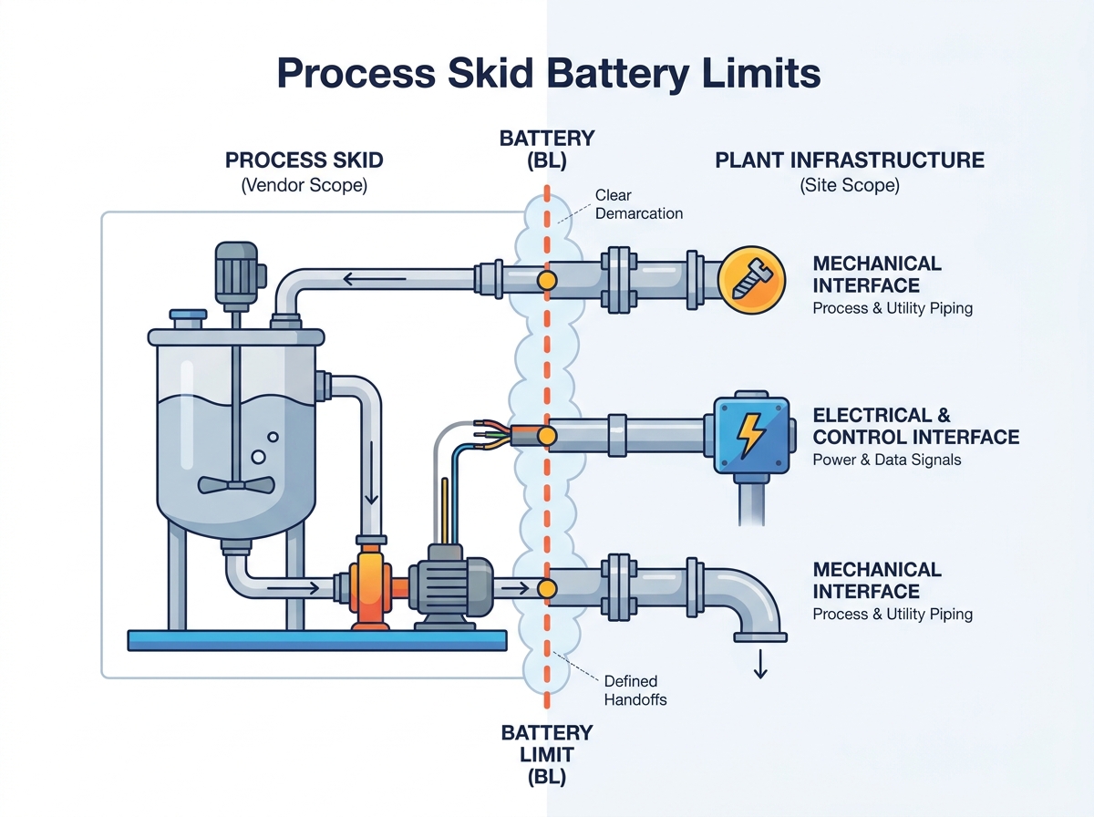
Clearly defining process skid battery limits prevents costly on-site modifications and unmanaged scope gaps during installation.
A comprehensive skid interface matrix is the most effective tool for aligning vendor deliverables with plant infrastructure across mechanical, electrical, and control disciplines.
Procuring a modular pump tank agitator package requires establishing precise utility, structural, and data hand-offs prior to the Request for Proposal (RFP) stage.
Evaluating skid vendors should heavily index on their Factory Acceptance Testing (FAT) capabilities and their approach to boundary documentation (P&IDs and 3D models).
Vague engineering parameters routinely sabotage capital projects. Writing a specification requiring the "vendor supplies piping" creates a massive integration blind spot. Plant engineers often assume vendors will route utilities to existing headers. Meanwhile, vendors assume plant operators will bring utilities directly to the skid edge. This misalignment guarantees costly delays.
Unplanned on-site welding destroys project timelines. Hot work permits require extensive safety reviews. Electrical rerouting drains your maintenance budget. Software integration bugs halt commissioning entirely. These operational surprises quickly ruin the return on investment for choosing a modular solution. Defining your process skid battery limits eliminates these expensive blind spots early in the design phase.
A successful module integration requires absolute clarity across three primary engineering disciplines. You must establish strict rules for mechanical, electrical, and automation hand-offs.
Mechanical precision: You need flange-to-flange exactness. Engineers must specify the exact size, pressure rating, and standard (such as ANSI or DIN) for every physical connection point.
Electrical distribution: Decide between a single point of power connection and distributed drops. A single main disconnect on the frame simplifies site installation immensely.
Automation demarcation: Create a clear boundary between the skid-mounted PLC or remote I/O block and your plant Distributed Control System (DCS). Handshake protocols must be pre-defined.
Front-loading your engineering hours pays massive dividends. Spending an extra fifty hours detailing tie-in points prevents hundreds of hours of site rework. Clear boundaries exponentially reduce your active commissioning time. Furthermore, accurate documentation lowers your long-term operational expenses. Maintenance teams can easily identify where vendor liability ends and plant responsibility begins.
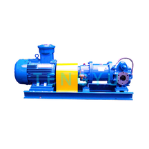
Procuring a combined system requires careful attention to multiple interacting boundaries. A pump tank agitator package features dynamic loads, pressurized fluids, and complex utility requirements. You must isolate each component and map its connection to the wider facility.
Vessels act as the central hub of your modular system. Inlet and outlet nozzle specifications must perfectly match your plant piping. Specify your required ANSI or ASME standards clearly. If a vendor supplies a flat-faced flange and your plant uses a raised-face flange, immediate leaks will occur.
Safety relief routing is another critical boundary. Determine who supplies the discharge piping for venting, overflow lines, and pressure relief valves (PRV). Dumping a PRV directly onto the skid deck presents a severe safety hazard. The plant must usually pipe these reliefs to a safe scrubber or atmospheric vent.
Mixing equipment introduces heavy dynamic forces. Structural support limits require careful negotiation. You must define whether the skid frame absorbs the agitator torque or if the vessel roof handles the loading entirely. Heavy industrial mixers can fracture vessel roofs if engineers ignore dynamic stress calculations.
Mechanical seals also demand dedicated utility boundaries. Dual mechanical seals require buffer fluid or barrier gas. You must specify the exact supply points for seal water or nitrogen. Clarify whether the vendor includes the seal pot system on the frame or if the plant provides it externally.
Fluid transfer systems rely on precise hydraulic conditions. Suction and discharge piping limits must include exact physical coordinates for site tie-ins. Isolation valve placement determines maintenance safety. Decide if the main isolation valve sits on the module or on the plant header.
Net Positive Suction Head (NPSH) responsibilities often cause disputes. The vendor controls the NPSH required (NPSHr) based on pump selection. However, the plant controls the NPSH available (NPSHa) through external piping design. Both parties must agree on the hydraulic calculations before finalizing physical line routing.
Relying solely on piping diagrams is a common engineering mistake. To achieve flawless integration, you need a dedicated tracking document. A skid interface matrix serves as the authoritative spreadsheet governing every single tie-in point between the equipment vendor and the end-user.
Your matrix must categorize boundaries into specific functional groups. This prevents overlapping responsibilities and highlights missing connections.
First, document the process fluids. Track the product entering and exiting the module. Record expected flow rates, maximum pressure limits, and exact flange ratings for every product nozzle.
Next, define the utilities. Modular systems consume various plant resources. Specify the supply and return lines for instrument air, chilled water, plant steam, and clean-in-place (CIP) chemicals. Note the required pressure and temperature for each utility at the exact boundary point.
Finally, capture power and control details. Document precise voltage requirements. State clearly whether the Motor Control Center (MCC) resides on-skid or off-skid. List the specific communication protocols required, such as Ethernet/IP, Modbus TCP, or Profinet.
Interface Category | Specification Details | Vendor Responsibility | Plant Responsibility |
|---|---|---|---|
Process Fluid Inlets | 2" ANSI 150# RF Flange, 316SS | Provide mating flange at skid edge | Route pipe to flange, provide gasket |
Instrument Air | 90 PSI, 1/2" NPT Connection | Provide main air manifold on frame | Run tubing from header to manifold |
Main Power Supply | 480VAC, 3-Phase, 60Hz | Wire all motors to single junction box | Pull main feeder cable to junction box |
Data Communication | Ethernet/IP to Plant DCS | Provide mapped PLC data registers | Program DCS to read/write registers |
Effective matrices rely on explicit transparency. You must deliberately list what is not included in the vendor scope. If the vendor does not supply the anchor bolts for the frame, write it down. If the plant must supply the primary network switch, state it clearly. Documenting exclusions proactively prevents bitter vendor-client disputes during the final installation phase.
Theoretical boundaries look perfect on paper. However, physical implementation introduces complex engineering realities. You must manage dynamic forces, regulatory compliance, and testing limitations before the equipment ever leaves the shop.
Integrating heavy agitators and high-capacity pumps on a shared modular frame creates severe vibration risks. Harmonics can destroy piping welds. Resonance occurs when the natural frequency of the frame matches the operating speed of the mixer. The vendor must perform finite element analysis to guarantee structural stiffness. You must ensure the plant floor can handle these dynamic loads at the baseplate boundary.
Regulatory compliance introduces another layer of complexity. You must clarify responsibilities for site-specific compliance versus skid-level certifications. A vendor might supply an ASME U-Stamp for the pressure vessel. However, they cannot automatically guarantee full OSHA compliance for your specific facility layout.
Hazardous area classifications demand absolute clarity. If your plant requires ATEX or NEC Class I Division 1 compliance, the entire module must meet these standards. Ensure the vendor understands who signs the final intrinsic safety declarations at the electrical boundary.
The Factory Acceptance Test represents your last chance to verify boundaries. You must physically verify every connection limit during the FAT before the unit ships. Inspect flange sizes, check junction box locations, and test the PLC handshakes.
Sometimes, a vendor cannot simulate specific plant utilities at their facility. They might lack the high-pressure steam or specific thermal fluid your process requires. In these cases, you must establish a clear protocol for the Site Acceptance Test (SAT). Document exactly how and when these final utility boundaries will undergo performance testing.
Selecting the right fabrication partner determines your project trajectory. You should evaluate vendors based on their rigorous approach to boundary management. Do not simply choose the lowest bidder. Choose the vendor who actively protects your project scope.
Expert vendors behave differently during the bidding phase. Look for partners who proactively challenge your piping and instrumentation diagrams. They will not accept vague specifications. Instead, they will immediately request a detailed interface matrix. They want to know exactly where their liability ends. This proactive questioning indicates high engineering maturity.
Assess vendor in-house engineering capabilities carefully. A fabricator needs more than just welders. They require advanced 3D modeling expertise to ensure the module aligns perfectly with your physical site tie-ins. Ask about their stress analysis procedures. Verify their structural engineering credentials. They must prove they can design a rigid frame capable of supporting heavy dynamic loads.
To successfully procure your modular system, follow these structured steps:
Finalize the P&ID with clearly marked boundary limit clouds. Use dashed lines to explicitly separate vendor scope from plant scope.
Draft the comprehensive interface matrix. Detail every fluid, utility, and data point.
Issue the RFP to shortlisted vendors. Include a strict mandate requiring them to price all boundary connections transparently.
Review vendor proposals against the matrix to identify any hidden scope gaps.
The success of a modular process system hinges entirely on the clarity of its edges. Vague specifications lead to broken budgets and missing connections. When you precisely define your mechanical, electrical, and control boundaries, you protect your project timeline.
A well-defined fluid transfer and mixing package dramatically reduces site disruption. It accelerates your time-to-market and allows your team to focus on production rather than installation troubleshooting. Transparency always outperforms assumptions.
Take proactive control of your next capital project. Consult with engineering specialists today. Review your existing piping diagrams and finalize your interface matrices before locking in any procurement contracts. Establishing firm borders now guarantees a flawless installation later.
A: On a Piping and Instrumentation Diagram, battery limits represent the visual boundary line. Engineers typically draw a dashed cloud or a specific demarcation line across the pipes and wires. This line clearly shows exactly where the skid vendor's responsibility ends and the plant's permanent infrastructure begins.
A: The skid vendor typically provides the termination point. They supply a flanged connection, threaded port, or an electrical junction box at the skid edge. The plant or site contractor is then responsible for physically routing the facility utilities directly to that exact termination point.
A: P&IDs only show logical flow and general components. They lack physical details. An interface matrix defines exact physical coordinates, communication protocols, voltage specifics, and physical mating standards. These critical details ensure equipment physically fits together, which standard P&IDs often omit entirely.
A: There are two common approaches. First, the module can include an on-skid PLC that handshakes with the plant DCS via a network protocol like Ethernet. Alternatively, vendors install remote I/O blocks on the skid frame, which operators hardwire back to the plant's central control panel.