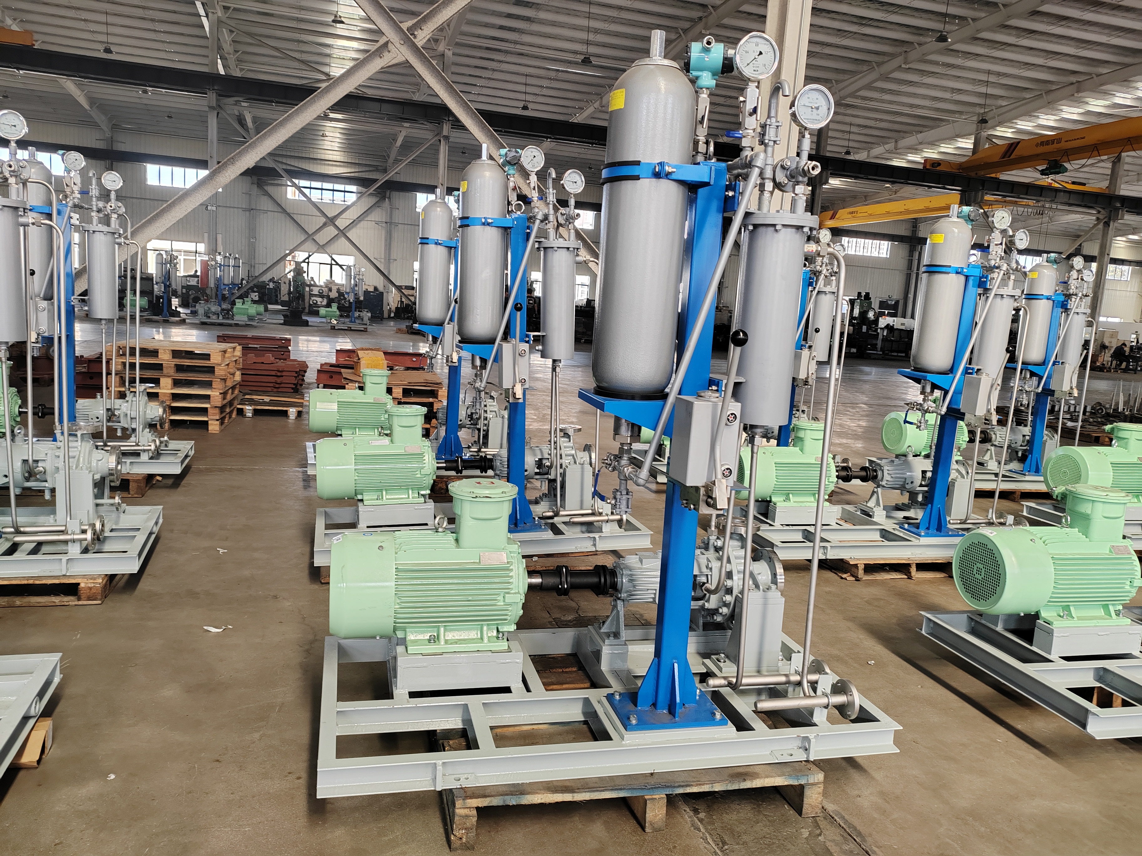
Process duty brings incredibly high stakes to industrial facilities. Equipment failure in hydrocarbon or heavy chemical processing leads to unacceptable downtime. It creates severe safety hazards and massive environmental liabilities. You simply cannot afford miscalculations in these critical environments. Sizing an API 610 pump goes far beyond basic hydraulic fits. It requires balancing operational flexibility alongside strict adherence to API 610 (ISO 13709) mechanical and metallurgical requirements.
We wrote this guide to provide process engineers and procurement teams with a definitive framework. You will learn step-by-step how to specify, size, and evaluate API 610 process pumps. Our approach eliminates guesswork and builds a robust foundation for your procurement strategy. By the end, you will know exactly how to ensure long-term reliability and strict compliance for your most demanding industrial applications.
Inaccurate initial data creates a domino effect. These early errors compound rapidly during pump selection. They result in off-design operation, excessive maintenance, or even catastrophic mechanical failure. A robust sizing process always begins by framing the exact business problem. You must capture reality, not just theoretical ideals. Engineers often rely on a single design point. This approach ignores process fluctuations and ultimately harms reliability.
Fluids behave differently under varying thermal conditions. You must map these variations thoroughly. Standardize your datasheet using precise measurements across all operating extremes.
You must map static head and dynamic friction losses accurately. Map them across the entire anticipated operational range. Do not just plot the single rated point. Control valves throttle flow, changing the system curve dynamically. Strainers clog over time, increasing friction losses. Proper API 610 pump sizing accounts for these realities. You need a comprehensive system resistance curve. It shows exactly where the pump performance curve intersects your actual process demands. This intersection dictates real-world efficiency.
Hydraulic selection separates a reliable pump from a maintenance nightmare. Process duties demand stability. You achieve stability by keeping the pump within its preferred operating region.
API 610 guidelines strongly recommend operating between 80% and 110% of BEP. Operating too far left of BEP causes internal flow recirculation. This recirculation generates high radial thrust, severely deflecting the shaft. Shaft deflection destroys mechanical seals and bearings. Conversely, operating too far right of BEP increases fluid velocity tremendously. This leads to choke flow, severe vibration, and immediate cavitation risks. You must select an impeller profile aligning closely to your normal process flow.
Chart 1: Operational Zones and Associated Mechanical Risks
| Operating Zone | Flow vs. BEP | Primary Mechanical Risks | API 610 Recommendation |
|---|---|---|---|
| Left of BEP | Below 70% | Suction recirculation, high radial thrust, premature seal failure | Avoid continuous operation |
| Preferred Operating Region | 80% to 110% | Minimal vibration, optimal shaft stiffness, longest bearing life | Target zone for normal duty |
| Right of BEP | Above 110% | Cavitation, high vibration, NPSHr exceeding NPSHa | Restrict usage |
Net Positive Suction Head coordination prevents fluid boiling inside the impeller eye. Standard industry practices dictate maintaining a safe margin between NPSHa and NPSHr (Required). We typically mandate a minimum 1-meter margin. Alternatively, use a 1.1 to 1.5 ratio depending on fluid volatility and pump energy density. High-energy pumps demand larger margins. Failing to secure this margin guarantees cavitation. Cavitation rapidly erodes impeller vanes and compromises hydraulic performance.
Process demands fluctuate. You must protect the pump during low-demand conditions by establishing Minimum Continuous Safe Flow limits. Two distinct MCSF types exist:
Stable MCSF is almost always higher than Thermal MCSF. Avoid oversizing your pump. Oversized pumps run chronically near MCSF. This forces you to install bypass lines, complicating the system and wasting energy.
You cannot solve every process problem using a standard overhung pump. Aligning the physical pump structure to process severity ensures mechanical longevity. API 610 categorizes pumps into specific structural families.
OH2 pumps feature a centerline-mounted casing and a single-stage overhung impeller. They represent the workhorses of the refining industry. They handle standard process duties perfectly. OH2 units accommodate moderate pressures and typical temperatures up to 400°C. They offer an excellent balance of reliability and manageable footprint. OH3 units offer an inline vertical configuration. Choose OH3 when footprint constraints dictate piping arrangements. Keep in mind, overhung designs have limits regarding shaft deflection under heavy loads.
High-energy, high-pressure, or extreme-temperature transfers require Between Bearings (BB) pumps. BB2 pumps utilize single or two-stage radially split casings. They handle aggressive hot oil applications safely. When rotor dynamics demand multistage configurations for massive pressure boosts, BB3 (axially split) or BB5 (barrel casing) pumps become mandatory. The simply supported shaft design of BB pumps drastically reduces shaft deflection. This structural rigidity protects bearings during transient process upsets.
Sump applications or systems suffering from critically low NPSHa require Vertically Suspended pumps. VS4 units serve well in open sump pits. VS6 units utilize a "canned" multi-stage approach. The can essentially lowers the first-stage impeller below grade. This artificially increases the static suction head, resolving severe NPSHa deficiencies. We heavily evaluate barrel length and column resonance when specifying VS6 configurations to prevent structural vibration.
Hydraulic selection is only half the battle. Integrating the pump into the physical plant introduces complex mechanical risks. Overlooking these implementation factors voids operational reliability.
Process piping expands and contracts due to thermal changes. These thermal movements transfer immense forces and moments directly onto the pump nozzles. Your selected pump casing must withstand these nozzle loads without distorting. Casing distortion causes internal rubbing and immediate mechanical failure. We highly recommend integrating pump selection software alongside piping stress analysis tools like CAESAR II. This digital coordination ensures piping engineers route lines properly to prevent excessive casing strain.
The mechanical seal represents the primary defense against hazardous leaks. API 610 mandates specific seal chamber dimensions to accommodate API 682 mechanical seals. You must ensure the pump sizing supports the required seal arrangement. Single, double, or tandem seals require specific radial clearances. High-pressure double seals (Plan 53B or 54) add complexity. Your sizing choice must accommodate these arrangements without compromising the physical space around the bearing housing.
Shaft stiffness directly dictates mechanical seal life. We measure shaft stiffness using the L³/D⁴ ratio. Here, 'L' represents the cantilevered shaft length, and 'D' represents the shaft diameter at the seal face. A lower ratio indicates a stiffer shaft. High shaft stiffness minimizes deflection when the pump operates off-BEP. API 610 enforces strict limits on maximum allowable shaft deflection. Always scrutinize a vendor's proposed shaft diameter. A marginally thicker shaft dramatically improves seal and bearing longevity.
When evaluating manufacturers for an API 610 chemical transfer pump, you must look far beyond the base price. Strategic procurement requires assessing engineering pedigree, manufacturing capabilities, and quality assurance protocols.
Do not select vendors based solely on immediate availability. Evaluate their historical performance in similar aggressive process duties. Request reference lists for the specific API pump type and material class you intend to buy. A vendor excelling in water pumps might fail miserably when manufacturing a BB5 barrel pump for high-temperature hydrocarbons.
A reputable vendor offers a robust hydraulic map. They should provide a casing capable of accepting multiple impeller profiles. Does the vendor allow for future impeller adjustments? Process conditions often change years after initial commissioning. You want the ability to install a larger impeller without replacing the entire pressure casing. We look for vendors offering at least a 5% increase in head capability via maximum impeller diameter.
Never bypass Factory Acceptance Testing (FAT). Rigorous testing proves the equipment works before it reaches your site. Require a full performance test per API 610 acceptance criteria. Demand an NPSHr test if your suction conditions are marginal. Vibration testing is absolutely critical. The vendor must demonstrate that vibration levels remain well within API 610 limits across the entire preferred operating region. If a vendor lacks comprehensive in-house testing facilities, disqualify them.
Exotic metallurgy requires specialized foundry expertise. Assess the vendor's direct foundry access. Casting Super Duplex stainless steel or Hastelloy requires strict thermal controls. Poor casting quality leads to porosity and catastrophic pressure boundary failure. Scrutinize their track record regarding Non-Destructive Examination (NDE) documentation. They must provide flawless radiography or dye penetrant testing records for all critical casings. Understand their lead times for these specialized materials, as exotic alloys routinely delay project schedules.
Sizing an API 610 process pump demands absolute precision. You must transition carefully from technical hydraulic sizing to strategic procurement. Establishing accurate fluid properties sets the foundation. Matching those properties to a pump operating safely near its Best Efficiency Point guarantees mechanical stability. Selecting the correct structural configuration (OH, BB, or VS) ensures the unit withstands environmental and thermal stresses.
A conservative, well-documented approach to completing the API 610 datasheet minimizes headaches during commissioning. Do not rush the specification phase. Rigorous vendor evaluation guarantees you receive equipment capable of surviving decades in hazardous environments.
Take action today to secure your process reliability. Submit your process data sheets, fluid properties, and system resistance curves to your engineering team. Request a thorough technical review and preliminary pump selection to keep your project moving forward safely.
A: Oversizing is a common engineering error caused by adding too many safety margins. It forces the pump to operate far to the left of its Best Efficiency Point, often near Minimum Continuous Safe Flow (MCSF). This causes severe internal recirculation, high radial thrust, heavy vibration, and drastically shortened mechanical seal life.
A: High fluid viscosity increases internal friction. It reduces the pump's flow rate, generated head, and overall efficiency while increasing power consumption. You must apply performance correction factors per Hydraulic Institute standards to ensure the selected motor and impeller can handle the viscous drag.
A: Thermal minimum flow is the absolute lowest flow rate needed to dissipate internal heat and prevent the process fluid from boiling. Stable minimum flow is the rate required to prevent damaging internal recirculation and mechanical vibration. Stable minimum flow is typically much higher and dictates operational limits.
A: API 610 pumps feature much heavier casing walls to withstand high pressures and corrosion. They include strict allowable nozzle load limits, centerline mounting to handle thermal expansion, and require rigorous Factory Acceptance Testing. These robust features ensure maximum reliability and safety in hazardous process duties.