Processing pseudo-plastic fluids presents a severe engineering challenge in industrial mixing. As the shear rate drops further away from the impeller, fluid viscosity spikes dramatically. This rapid change creates stagnant caverns and unmixed zones within the vessel. Standard turbine agitators fail to provide adequate bulk fluid movement in these high-viscosity applications. You must rely on close-clearance impellers to physically force material motion. Without them, operators face ruined batches, inconsistent reactions, and poor thermal control. We will explore the critical decision-making framework for engineers evaluating a helical ribbon vs anchor shear thinning solution. You will learn how to balance mixing efficiency, power consumption, and mechanical constraints. By the end, you can confidently select the right equipment for your toughest viscous formulations.
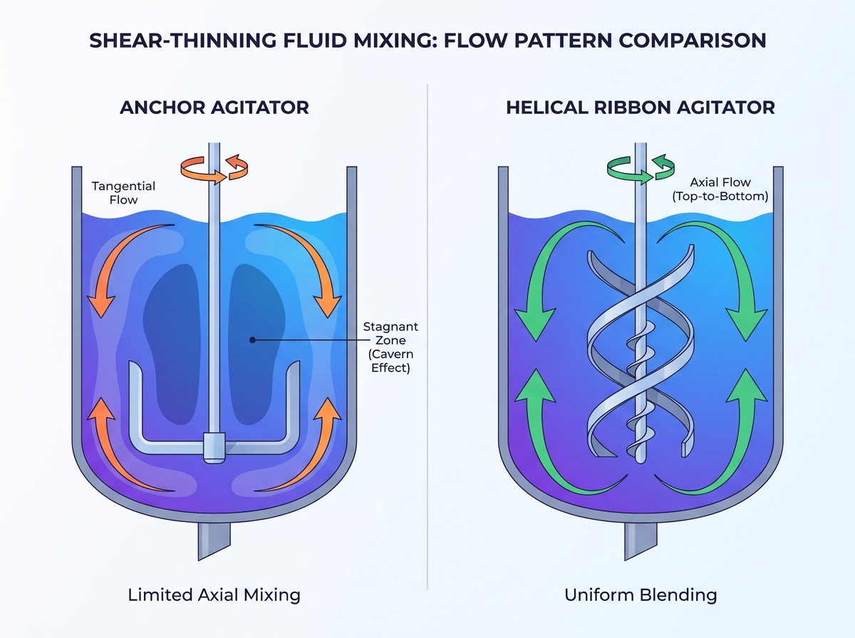
Anchor agitators excel at wall-scraping and heat transfer but struggle with vertical (axial) turnover in highly viscous states, often leaving stagnant zones in the center of the vessel.
Helical ribbon agitators drive active top-to-bottom (axial) flow, eliminating dead zones and ensuring uniform distribution in extreme viscosity ranges.
Decision Matrix: The choice hinges on the fluid's apparent viscosity at rest, the requirement for axial blending, and the allowable mechanical torque on the drive system.
Power Consumption: Helical ribbons generally require higher power inputs and present higher upfront fabrication costs, demanding precise power correlation calculations before scale-up.
Shear-thinning fluids behave unpredictably during mechanical agitation. Polymer dopes, pharmaceutical gels, and food purees share this unique trait. They exhibit a high apparent viscosity when at rest. Mechanical agitation introduces localized shear forces into the fluid matrix. High shear at the blade edge lowers viscosity locally. However, the bulk fluid further away remains highly viscous. This pseudo-plastic behavior complicates standard mixing models. To overcome this rheological hurdle, engineers must implement a dedicated non Newtonian mixer design. Standard pitched-blade turbines simply cannot penetrate the thick outer layers of the fluid.
Inadequate impeller selection inevitably leads to localized mixing. Industry experts call this the "cavern effect." The agitator blades carve out a well-mixed hole inside the fluid matrix. The fluid inside this cavern spins rapidly due to reduced viscosity. Meanwhile, the material near the vessel walls and the center remains completely stationary. These unmixed regions ruin product homogeneity. They also trap heat, creating dangerous thermal gradients. You cannot rely on fluid momentum to carry the mixing action to the vessel extremities. The physical reach of the impeller dictates the actual mixing volume.
Engineers solve the cavern effect by expanding the impeller diameter. Both anchor and helical ribbon designs represent close-clearance solutions. Their outer edges sweep within millimeters of the vessel wall. This extreme proximity mechanically forces fluid movement. Shear forces alone cannot move yield-stress fluids across large distances. The physical presence of the sweeping blades physically displaces the material. This design strategy ensures no fluid can remain permanently stagnant at the boundary layer. Close-clearance impellers dominate high-viscosity applications for this exact reason.
Anchor agitators feature a distinct U-shaped geometry. They conform tightly to the bottom and sides of the mixing vessel. This shape generates a primarily tangential flow pattern. The blades push the fluid in a continuous rotational path. They scrape or sweep the fluid layer directly adjacent to the vessel wall. This action prevents material from baking onto heated surfaces. Tangential flow works well for keeping the outer fluid layers active. However, it does very little to move material up or down the shaft.
Anchor agitators perform exceptionally well under specific operating conditions. They shine when thermal management takes priority over rapid blending. Engineers typically specify anchor designs for the following scenarios:
Applications requiring continuous wiping of the vessel wall to prevent thermal degradation.
Processes demanding high heat transfer rates through a jacketed vessel.
Fluids exhibiting moderate apparent viscosities.
Operations where secondary flow patterns still naturally occur due to lower yield stresses.
Cost-sensitive projects requiring straightforward fabrication and easier maintenance.
Despite their utility, anchor agitators exhibit severe performance limitations in extreme viscosities. You must recognize these boundaries to avoid batch failures. The core issues stem from their geometric simplicity. The limitations include:
Lack of Axial Flow Generation: Anchors cannot drive fluid vertically along the shaft.
Solid Cylinder Spinning: In highly shear-thinning fluids, the anchor spins the entire fluid mass as one solid block.
Central Stagnation: The center of the vessel experiences almost zero turnover, causing severe stratification.
Extended Mixing Times: Achieving a tight coefficient of variation takes significantly longer due to poor central engagement.
Helical ribbon agitators utilize a complex, dual-action geometry. Continuous helical flights wrap around the central shaft. These outer ribbons pump fluid downward along the vessel wall. This downward displacement creates a pressure differential at the vessel floor. The pressure forces a corresponding upward flow right through the center of the vessel. Some designs incorporate an inner ribbon pitched in the opposite direction. This inner flight actively pulls the central fluid upward. This push-pull mechanism generates a massive, continuous axial circulation loop.
Engineers specify helical ribbons when fluid rheology defeats simpler impellers. These agitators excel in environments demanding complete bulk homogeneity. They handle the toughest industrial formulations with ease. Ideal applications include:
High to ultra-high viscosity polymer formulations and resins.
Processes requiring strict compositional uniformity across the entire batch.
Reactions demanding precise thermal uniformity without localized hot or cold spots.
Operations mixing highly shear-sensitive materials requiring low rotational speeds.
Formulations where resting viscosity exceeds 100,000 centipoise.
The geometric complexity of the helical ribbon delivers unmatched process benefits. It actively overcomes the core weaknesses of the anchor design. First, it virtually eliminates central dead zones. The central up-flow ensures every fluid particle eventually reaches the high-shear wall zone. Second, it maintains consistent bulk turnover. This turnover continues regardless of the fluid's resting viscosity. Third, the forced axial flow drastically reduces batch times. Operators achieve reliable product quality faster, increasing overall plant throughput.
When executing a viscous mixing comparison, blend time serves as the primary metric. We measure efficiency by the time required to achieve a defined coefficient of variation (CoV). Anchor agitators struggle to lower the CoV rapidly. Their reliance on diffusion for central blending extends mixing times exponentially. Conversely, helical ribbons achieve homogeneity significantly faster. The forced axial blending actively circulates the entire fluid mass. This macro-mixing action ensures chemical additives disperse evenly in a fraction of the time.
Power consumption calculations dictate the mechanical feasibility of your design. We examine the power number differences between the two geometries. Helical ribbons typically draw much more power at equivalent speeds. Moving heavy fluid vertically requires substantial energy input. You must specify robust gearboxes and larger drive motors. Engineers must carefully evaluate the Reynolds number thresholds. The transition from laminar to transitional flow dictates equipment sizing. In the deep laminar regime, power consumption scales linearly with viscosity. Calculating these correlations prevents catastrophic motor stalling during batch processing.
Heat transfer efficiency impacts both batch quality and processing time. Anchors are traditional favorites for heat transfer due to their sweeping action. They constantly renew the fluid layer against the jacketed wall. However, helical ribbons offer highly competitive thermal uniformity. They effectively replace the boundary layers with bulk fluid from the vessel center. This rapid surface renewal prevents localized scorching. While an anchor might achieve a slightly higher wall heat transfer coefficient, the ribbon ensures the entire batch maintains a uniform temperature.
Performance Metric | Anchor Agitator | Helical Ribbon Agitator |
|---|---|---|
Primary Flow Direction | Tangential (Rotational) | Axial (Top-to-Bottom) |
Viscosity Limit | Up to ~100,000 cP | Millions of cP |
Central Dead Zones | High Risk | Virtually Eliminated |
Power Consumption | Moderate | High |
Mixing Speed (Blend Time) | Slow | Fast |
Deploying close-clearance impellers introduces significant structural challenges. Both designs are heavy and operate under immense torque. Shaft deflection presents a constant threat to mechanical integrity. Bending moments can push the blades into the vessel wall, causing catastrophic failure. You must specify robust steady bearings or highly reinforced shaft designs to prevent deflection. Furthermore, process deviations cause dangerous viscosity spikes. If the shear-thinning fluid experiences unexpected temperature drops, the apparent viscosity skyrockets. This sudden resistance creates a severe risk of drive motor overload. Process engineers must interlock motor torque limits with thermal controls.
Sanitary environments demand rigorous cleaning protocols. The chosen impeller geometry directly impacts your CIP cycle times. We acknowledge the complex, sweeping geometry of a helical ribbon presents difficulties. The continuous flights create multiple shadowed areas. Cleaning fluid struggles to penetrate the tight intersections between the support arms and the ribbon. Validating the CIP process requires higher spray ball pressures and longer rinse cycles. Compared to the simpler, open framework of an anchor design, helical ribbons demand meticulous hygienic engineering.
Transitioning from a pilot plant to production capacity requires precise mathematical modeling. Simple geometric scaling often fails with yield-stress fluids. We emphasize the absolute necessity of Computational Fluid Dynamics (CFD) modeling. CFD accurately predicts flow patterns across varying vessel volumes. It identifies potential stagnant zones before metal is cut. More importantly, CFD validates the power requirements for the production-scale motor. Failing to model these parameters usually results in undersized drives or prolonged batch times at full scale.
Selecting the right impeller geometry dictates the success of your high-viscosity process. Anchor agitators provide a cost-effective choice for moderately viscous fluids prioritizing wall heat transfer. They keep the boundaries active but leave the center vulnerable to stagnation. Conversely, helical ribbons stand as non-negotiable solutions for highly viscous, shear-thinning applications. They force axial movement, guaranteeing complete bulk homogeneity. Before finalizing your mechanical design, you must secure rheological testing of your specific fluid. We advise running pilot-scale torque studies to map the apparent viscosity curve accurately. These steps ensure your CAPEX investment delivers the required mixing performance without risking mechanical failure.
A: While fluid-dependent, anchors typically lose efficiency when apparent viscosity exceeds 50,000–100,000 cP. Helical ribbons remain effective well into the millions of cP.
A: Yes, adding inner pitched-blade impellers or cross-arms (often called an anchor-gate or combined agitator) can induce some axial flow, though it rarely matches the efficiency of a true helical ribbon.
A: For a given diameter and speed in the laminar regime, a helical ribbon generally has a higher power number and requires a larger drive motor, reflecting the additional work of moving the bulk fluid vertically.
A: No. Baffles are typically omitted in high-viscosity laminar mixing as they interfere with the close-clearance blades and create stagnant zones behind the baffles.